This guide demonstrates the practical use of AI for monitoring meters (water meters, electricity meters, gas meters, etc.) and, more generally, for visual detection of environmental states.
The software AI-on-the-edge-device is developed by Josef Müller (alias jomjol).
Repository: https://github.com/jomjol/AI-on-the-edge-device
License: The project is available under a dual-license model – free for private/non-commercial use; for commercial deployment, a separate (paid) license must be arranged with the author. Always verify the current licensing terms in the repository before deployment.
In this example, we’ll demonstrate how AI can adapt to a specific environment and task. In addition to reading meter dials, the same principle can also be applied to state detection, for example:
- open/closed gates,
- presence of a vehicle,
- light/dark conditions,
- smoke or unusual visual changes.
The main limitations are image quality and your imagination regarding the specific use case.
Required hardware
We have two options:
A) our preconfigured initMAX AI kit (recommended for the workshop), or
B) custom hardware according to the minimum requirements below.
Note: The total cost of a DIY setup is typically around 10–20 USD (excluding mount/enclosure).
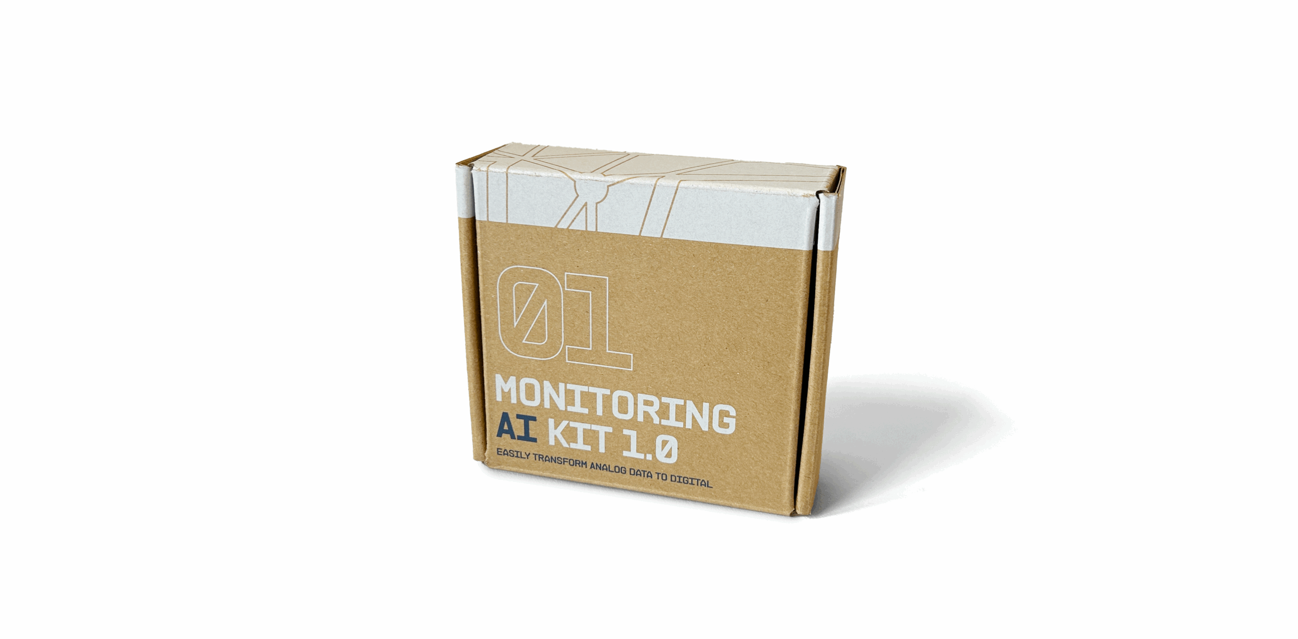
Option A: initMAX – MONITORING AI KIT 1.0
Includes everything needed in a tested combination: ESP32-CAM + OV2640, 8 MB PSRAM, ESP32-CAM-MB, microSD (FAT32), USB cable, mount, and power supply. You only need to set up Wi-Fi and upload the configuration.
Option B: Custom hardware – minimum requirements
- ESP32-CAM module (AI-Thinker or compatible) with PSRAM
- Recommended: 8 MB PSRAM (better stability and memory reserve).
- Minimum: a module with PSRAM; operation without PSRAM is significantly limited.
- Camera module OV2640
- A proven and well-supported option. Wider lenses are also available (useful for close-up imaging, but expect more distortion).
- ESP32-CAM-MB (USB programming/power board)
- Simplifies both power supply and flashing via USB-UART.
- USB cable
- Depending on the ESP32-CAM-MB version: Micro-USB (Micro-B) or USB-C (recommended).
- microSD card 2–32 GB (SDHC)
- FAT32 + MBR (not exFAT).
- Preferably Class 10.
- If the card “doesn’t work,” it’s typically due to format/partition issues (use FAT32/MBR and allocation unit size e.g. 32 KB).
- Power supply 5 V / min. 1 A
- A stable power source is crucial for both the camera and Wi-Fi.
- 2.4 GHz Wi-Fi connection.
- Camera mount/holder (tripod, 3D-printed mount, straps, etc.)
- Stability and consistent positioning greatly improve accuracy.
- Optional but useful:
- Additional lighting (consistent illumination dramatically improves results)
- Enclosure (3D-printed / weather-resistant)
- PoE power with 5 V step-down converter
Tip for lens focusing (important)
The manufacturer often secures the lens thread with a drop of varnish or glue. Before the first focusing, it’s necessary to gently loosen the thread (for example, using a fingernail, small pliers, or a printed focus ring).
Without proper focusing, recognition accuracy will be significantly reduced.
In our AI kit, however, this adjustment has already been done for you – the lens is tested, loosened, and ready for fine-tuning, so you don’t need to deal with any loosening yourself.
Preparing the SD card
In our kit, the SD card is preconfigured – it contains all the necessary files, including the wlan.ini configuration file with Wi-Fi settings. Therefore, there’s no need to modify anything or reformat the card.
However, if you want to prepare the card yourself, it must be formatted to FAT32 (MBR).
Example for Windows
Use the diskpart command (warning – this will erase all data on the selected disk!):
diskpart
list disk
select disk X   (nahraďte X číslem vaší SD karty)
clean
create partition primary
format fs=fat32 quick
assign
exit
Example for macOS
Use diskutil (warning – this will erase all data on the selected disk!):
diskutil list
diskutil eraseDisk FAT32 CAM MBRFormat /dev/diskX
(replace diskX with your card’s number; the volume name here will be CAM)
Example for Linux
Use mkfs.vfat:
lsblk
sudo umount /dev/sdX1
sudo mkfs.vfat -F 32 -n CAM /dev/sdX
(replace /dev/sdX with your SD card, e.g. /dev/sdb)
If your SD card is prepared and formatted, download the installation package containing the necessary data for the card. You can find the package in the Releases section at:
👉 https://github.com/jomjol/AI-on-the-edge-device/releases/
In the Assets section, look for a file named something like:
AI-on-the-edge-device__manual-setup__XXXXXX.zip
This ZIP archive contains the file sd-card.zip.
Extract the entire archive and copy its contents to the SD card (into its root directory).
Finally, open the wlan.ini file and adjust the Wi-Fi settings according to your network.
initMAX AI kit 1.0
If you have our AI Kit 1.0, you already have everything you need – including a test mount for the device.
The kit also includes a preconfigured SD card, which does not need to be formatted.
The card already contains the wlan.ini file with the device’s Wi-Fi settings, IP address, and hostname.
Device assembly
Open the box and check that everything inside matches the picture and that nothing is missing.
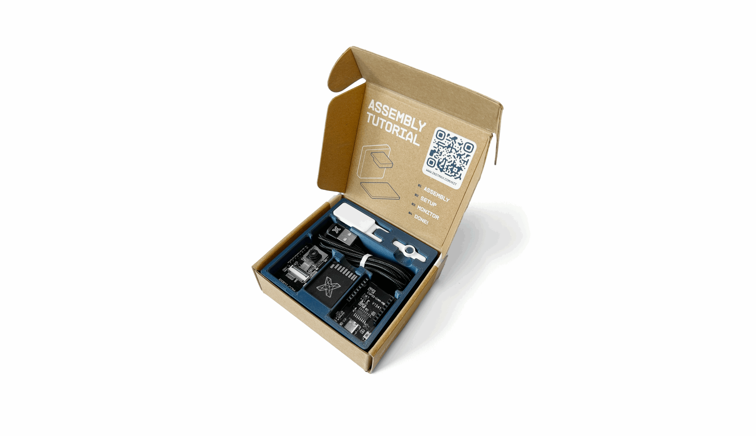
- At the top of the package, you’ll find a small tool for loosening or tightening the camera.
- A USB-C cable with a USB-A adapter is included for greater compatibility with different devices.
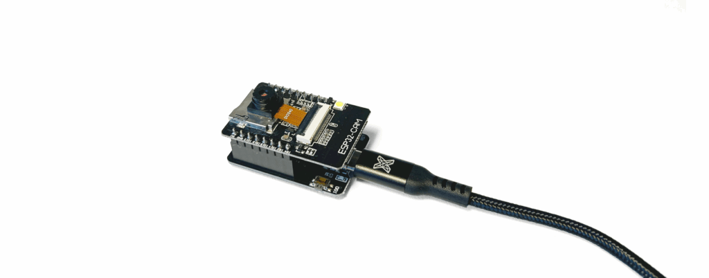
- At the bottom left is the ESP32 module with the camera already mounted and secured.
- In the middle, you’ll find a microSD card with a preinstalled base image.
- On the right is the ESP32-CAM-MB development board, which will be used to power the device via the USB cable.
- This connector also serves as a basic debug console and can be used for firmware flashing if needed.
Assembly
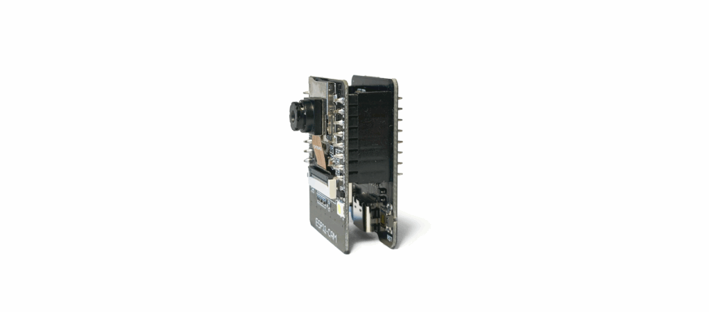
First, let’s assemble the components – the ESP32 module and the ESP32-CAM-MB development board.
Both parts must fit together firmly, as shown in the picture.
The number of pins exactly matches the counterpart – make sure all pins are fully inserted and properly aligned.
Next, remove the SD card, which is inserted into an adapter – for demonstration purposes, the adapter is set to the locked (write-protected) position.
If you want to modify the card later, you’ll need to unlock it.
Take out the microSD card from the adapter and carefully insert it into the slot on the ESP32.
Insert the card with the logo facing up, pushing it all the way in until you hear a click from the locking mechanism.
The card will then stay securely in place.
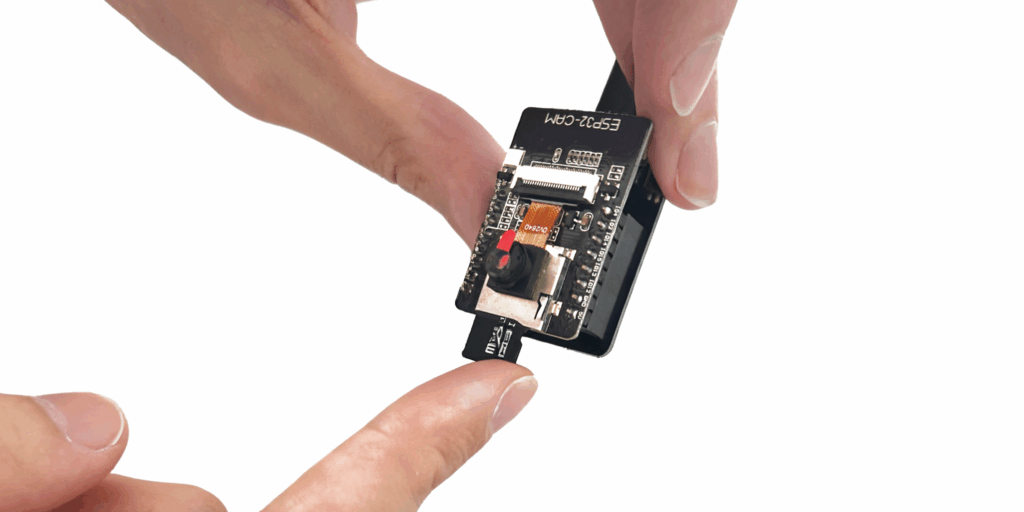
If you need to remove it, gently press on the card – the lock will release, and the card will pop out.
Do not pull the card out by force to avoid damaging the SD slot. Next, unpack the USB cable, which is secured with a rubber strap.
Find the end of the cable without the adapter and carefully insert it into the ESP32-CAM-MB development board.
The connector should slide in without excessive force, just until it clicks securely into place.
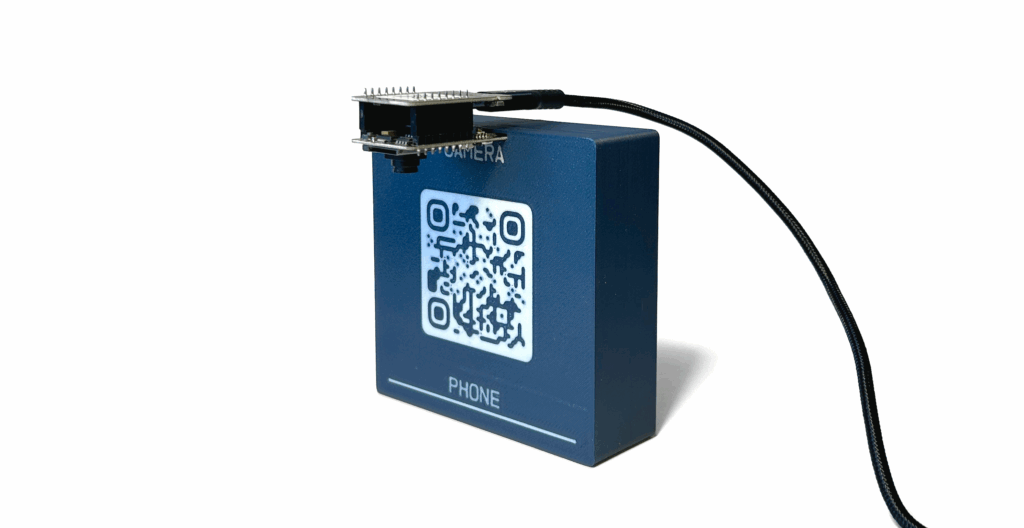
Now, remove the colored insert in initMAX colors.
On its back side, you’ll see two labeled slots: PHONE and CAM.
Carefully insert the ESP32 module into the CAM slot – the camera should face downward, and the initMAX logoshould remain clearly visible.
Only insert the ESP32 module itself, not the development board (DevBoard).
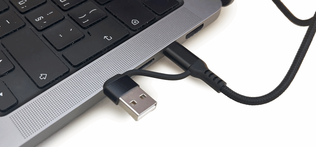
Now connect the USB cable to your computer.
We recommend using the USB-C connector if your computer supports it.
If necessary, use the included adapter – first plug it into the cable, and then carefully connect it to your computer.
On your phone, open our YouTube video that demonstrates one hour of water meter measurement.
You can start the video either by scanning the QR code or by visiting the web address provided.

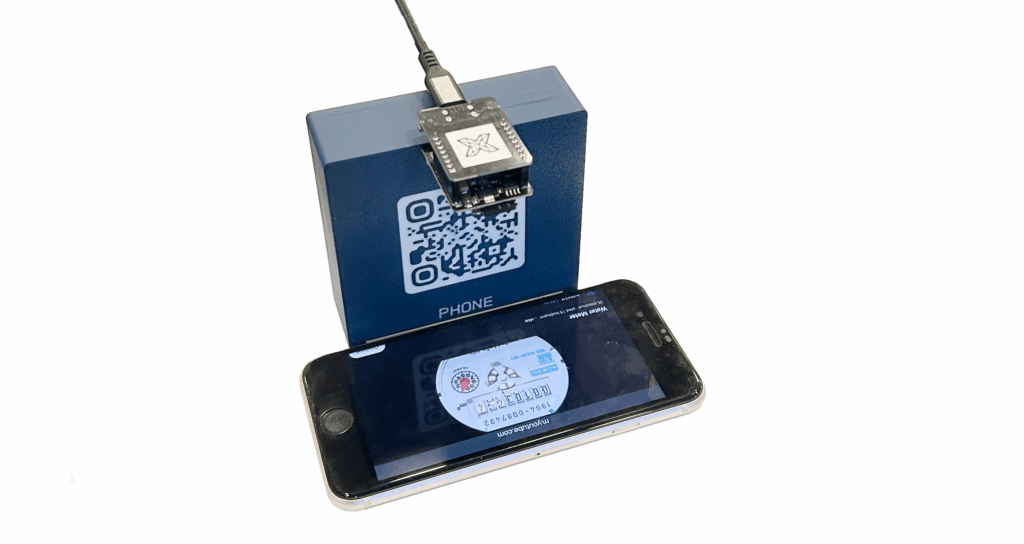
Once the video is playing, position your phone so that it is clearly visible to the ESP32 camera. For proper alignment, use the label and the white guideline marked on the base.
Your hardware setup is now complete, and you can proceed to the next step – device configuration.
⚠️ WARNING: The device and the phone must not move during the measurement.
Place them so that they are stable and there is no risk of movement.
If necessary, you can use something like a paper box for support.
Finding the IP address and first startup
During the first startup, it’s necessary to upload the firmware to your ESP32.
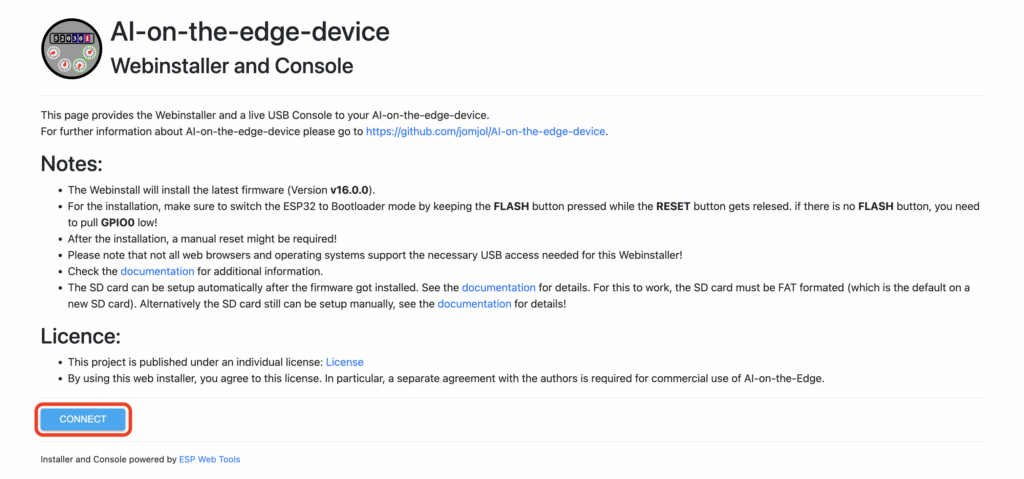
The easiest way is to use the web installer, available at:
👉 https://jomjol.github.io/AI-on-the-edge-device
⚠️ Note: The installer works only in Google Chrome – other browsers are not supported.
On the page, click the “Connect” button and follow the instructions.
It’s quite likely that the “ESP32 (USB-Serial)” device will not appear in the connection menu.
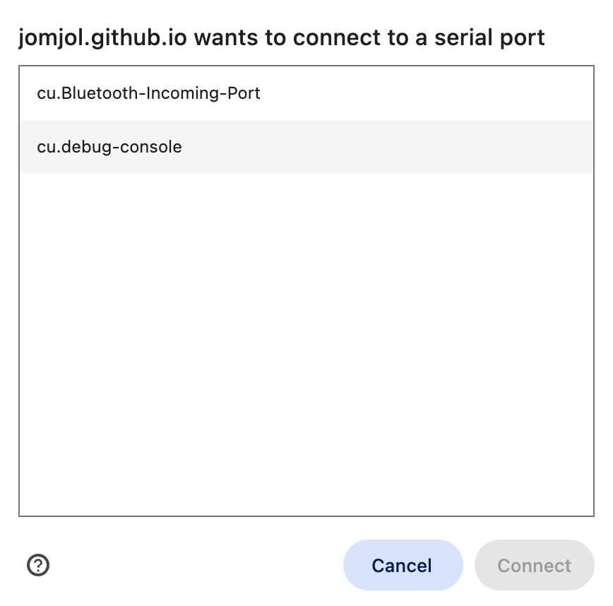
This means that the required drivers are not installed.
If you close the connection window, a popup will automatically appear offering to download the necessary drivers.
Our device uses the CH340C chip, so select CH340 for your operating system and install it.
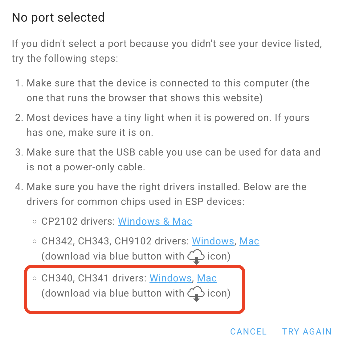
After installing the driver, it’s recommended to restart your browser (or the entire computer) and then try connecting again using the “Connect” button.

Click the “CONNECT” button again – your device should now appear in the list of available ports and be ready for firmware upload.
From the menu, select the first option “Install AI-on-the-Edge.”
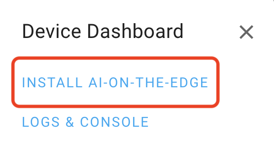
In the next window, confirm the installation by clicking the “Install” button.
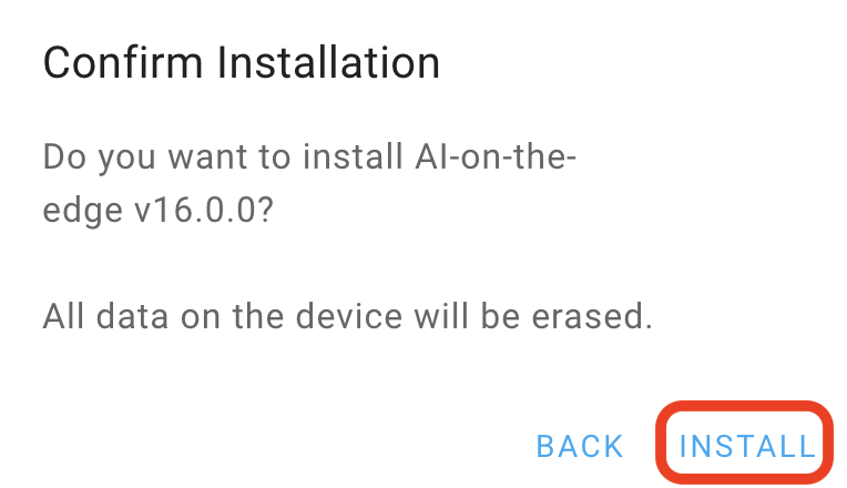
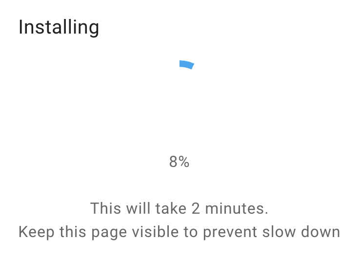
During installation, do not interrupt the process or close the browser window.
After a short moment, a progress bar will appear, indicating the firmware upload in progress.
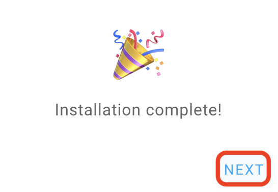
After a successful installation, the device will automatically restart.
Once it starts up again, we can switch to the second console and continue with the setup. Click the NEXT button.
Now switch to “Logs & Console.”
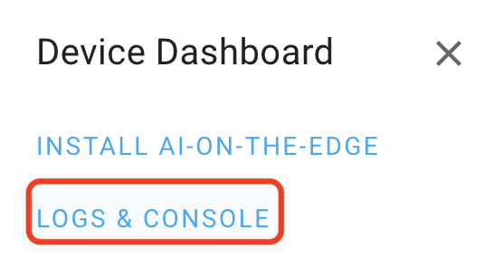
In this console, you’ll see useful information – for example, the boot process of the device, any SD card issues, or the network configuration, which is the most important for us at this stage.
There is also a “Reset” button – press it to view the boot sequence in progress.
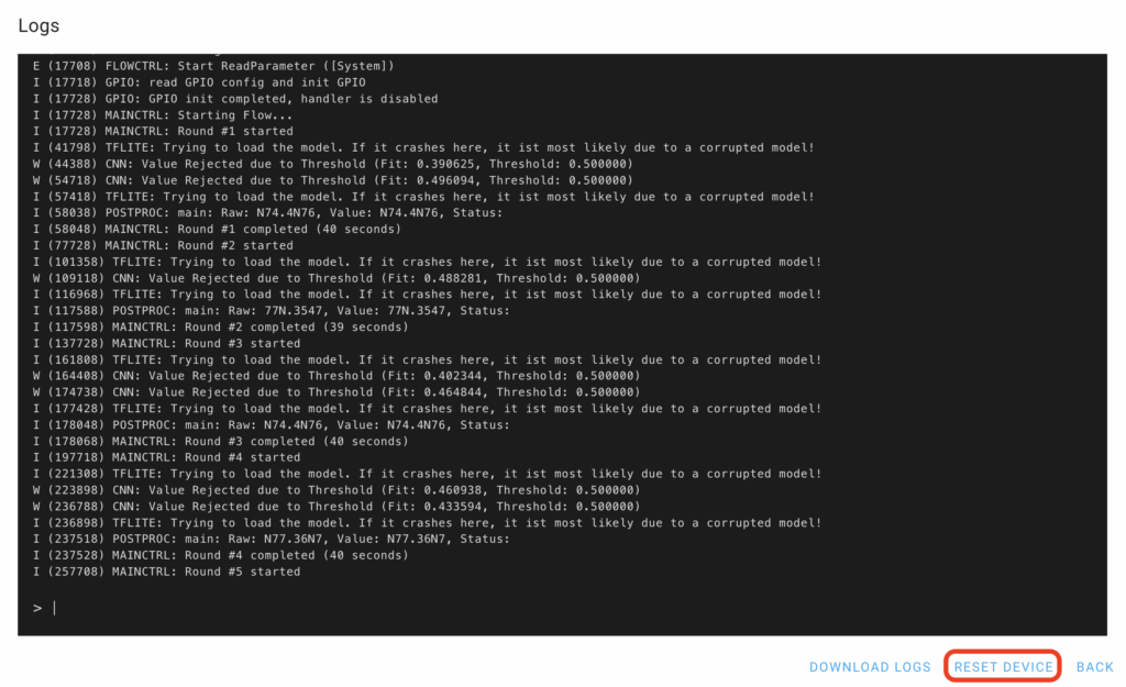
Note: The network configuration of each device is defined by the contents of the wlan.ini file.
You can modify this configuration at any time by manually editing the file directly on the SD card.
In our example, we see the following line:
I (10138) esp_netif_handlers: sta ip: 10.10.3.105, mask: 255.255.252.0, gw: 10.10.1.1
I (10138) WIFI: Assigned IP: 10.10.3.105
The value after Assigned IP: is the IP address of your device.
To connect to this IP address, you must be on the same Wi-Fi network.
In our case, this is the workshop Wi-Fi, and the login credentials can be found on the provided card.
(Each participant has their workshop number listed in the upper right corner.)
⚠️ Note: The Wi-Fi credentials are intended solely for the purposes of the workshop and will be deleted after it concludes.
After connecting to the workshop Wi-Fi, keep the debug log window open and, in a new browser tab, open the AI-on-the-Edge web interface:
http://10.10.0-3.XXX/ (replace with your device’s IP address)
Please ignore any version mismatch message for now. The upgrade process will be demonstrated later if time permits during the workshop.
Metter setting
Before we can continue, we’ll temporarily skip the setup wizard (we’ll return to it later). Now, let’s make two important adjustments:
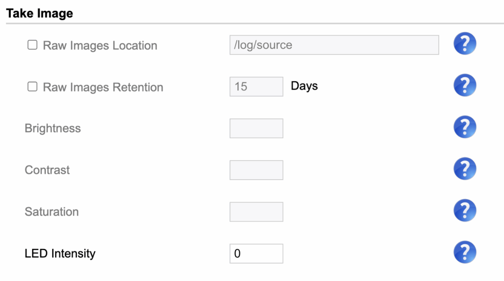
- Instead of using the wizard, please enter the following address in your browser: http://10.10.0-3.XXX/edit_config.html
- Here, set Take image → LED Intensity = 0 (this is mainly done for the workshop to prevent glare from phone screens).
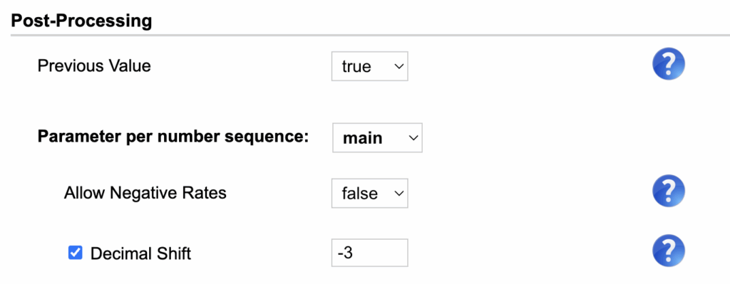
- In the Post-Processing section, set Decimal shift = -3 (because the first part of the meter display contains three decimal places).
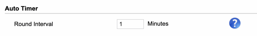
- In the Auto Timer section, set Round interval = 1 (this value determines how often the system will attempt to process the measured value).
At the bottom of the page, click Save Config, and then click Reboot Now. Alternatively, you can enter http://10.10.0-3.XXX/reboot in your browser to send a reboot request to the device.
After the restart, go back to the section and open the address: http://10.10.0-3.XXX/setup.html
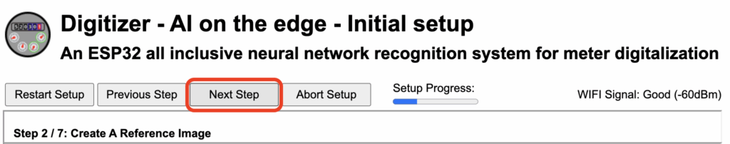
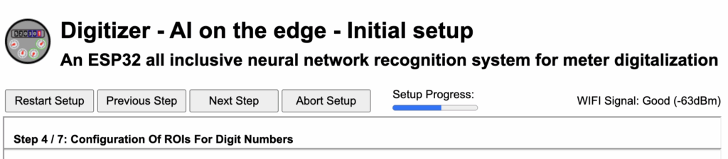
Note: Since we have the basic prerequisites for our lab configured, we can now proceed with the setup wizard. It’s important to save your changes after each step!
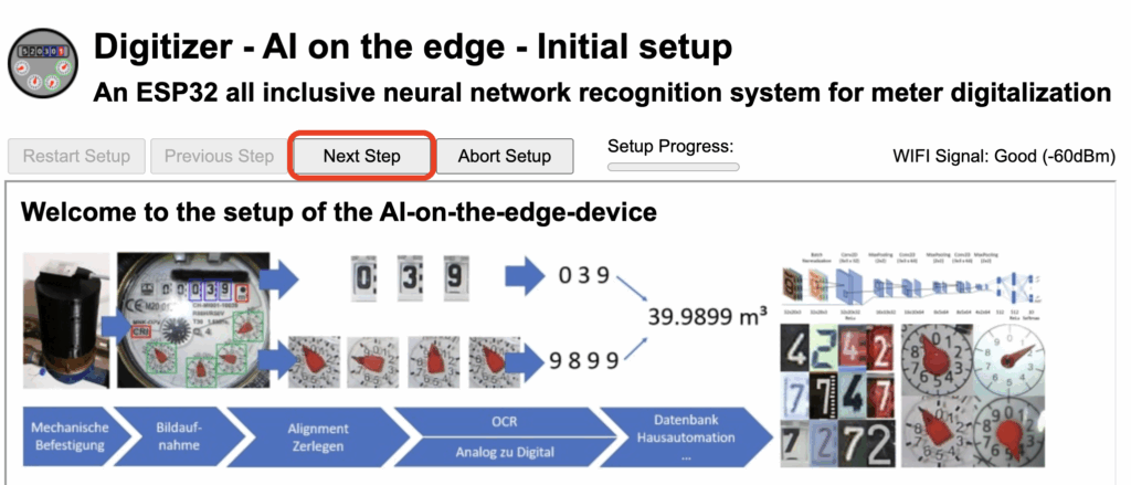
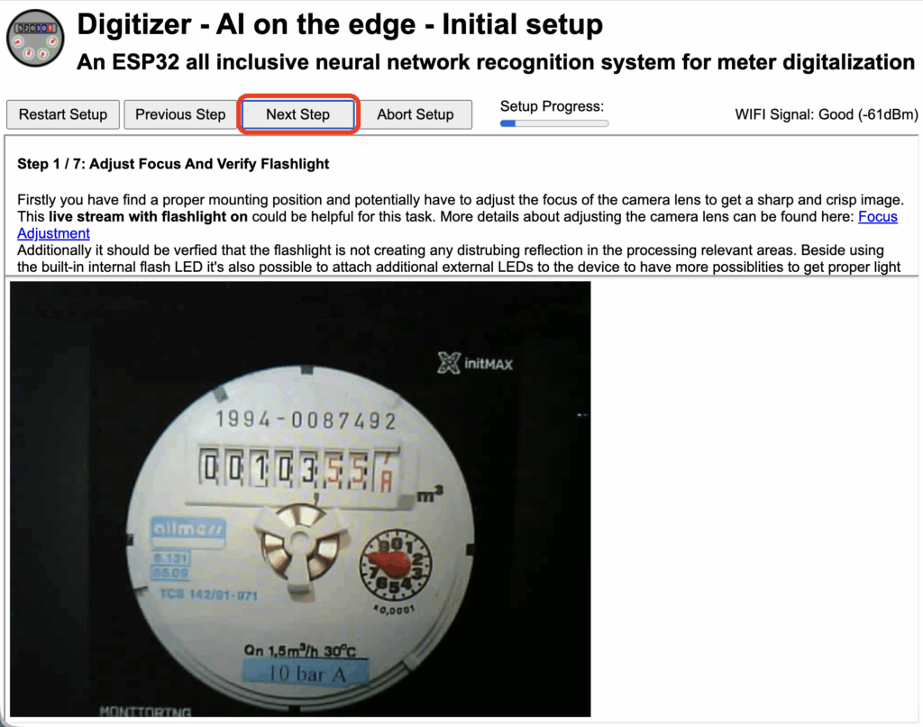
Click Next Step, where you’ll see how your image is being captured.
Now is the ideal time to position your phone in a suitable place and adjust the focus by rotating the lens (you will most likely need to tighten the lens rather than loosen it).
Once you’re satisfied with the image, you can proceed to the next step by clicking the Next Step button.
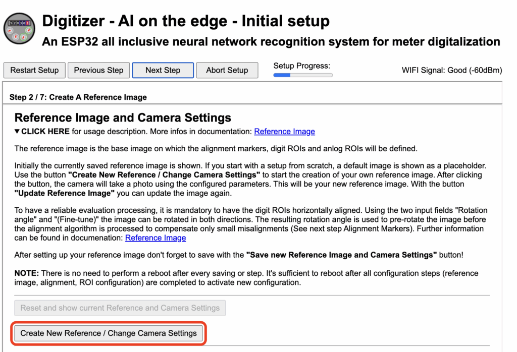
The first step is to capture a test static image of your meter.
Click the Create New Reference / Change Camera Settings button and wait a few seconds for the image to load.
Next, the image will need to be slightly adjusted.
There is also a button that allows you to rotate the image, along with a very useful green pointer that can be placed at the top of the display windows. This helps you align the image precisely.
Once the pointer is correctly positioned, adjust the image rotation using Rotation angle + (Fine-tune).
When everything is properly aligned and looks correct, click Update Reference Image.
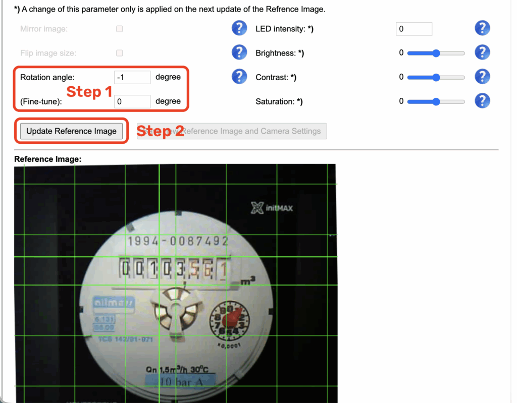
Then save the settings by clicking Save new Reference Image and Camera Setting.
Please do not underestimate this step – the accuracy of all subsequent configuration phases depends on it.

After saving, continue by clicking the Next Step button.
In this section, you’ll set up alignment markers, which tell the device how the image is aligned.
Note: this step includes two alignment markers, and both must be configured and saved separately.
To configure, select Marker 1 in the Marker section and focus it on the value 1994. Then click Update Marker, followed by Save New Marker.
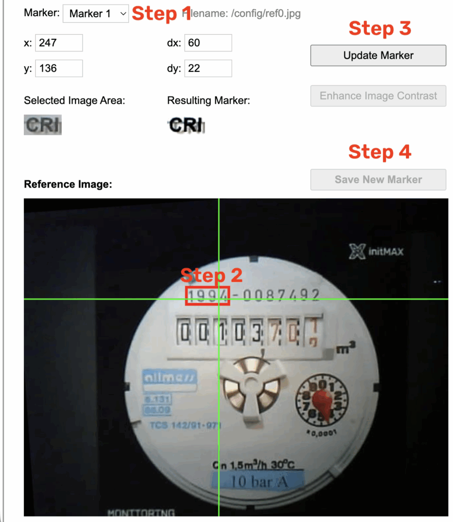
After saving, move on to Marker 2, focus it on m3, and again don’t forget to click Update Marker, then Save New Marker.
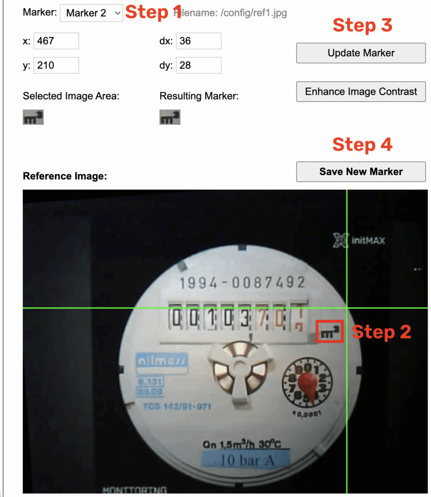
After saving, proceed to the next step by clicking the Next Step button.
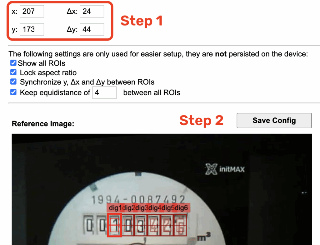
In this section, we’ll configure the windows for reading numerical values.
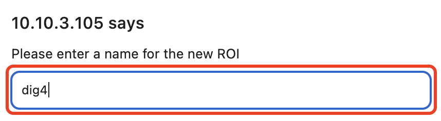
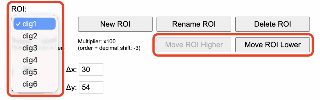
By default, only three fields are available. Using the New ROI button, add three more and name them dig4 – dig6.
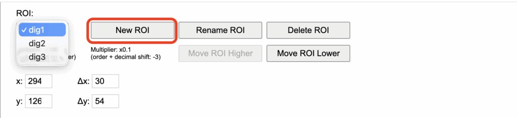
Use the same naming convention: dig4 – dig6.
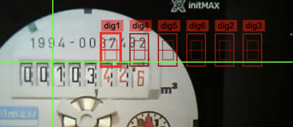
An important part is ensuring the correct ordering of these windows.
Use the Move ROI Higher and Move ROI Lower buttons to adjust their positions.
The order must be 1–6 – no values should be skipped.
Once everything is ready, mark dig1 as the field showing the first visible digit – in our case, 1 (from the value 001). We ignore the leading zeros to speed up the workshop process.
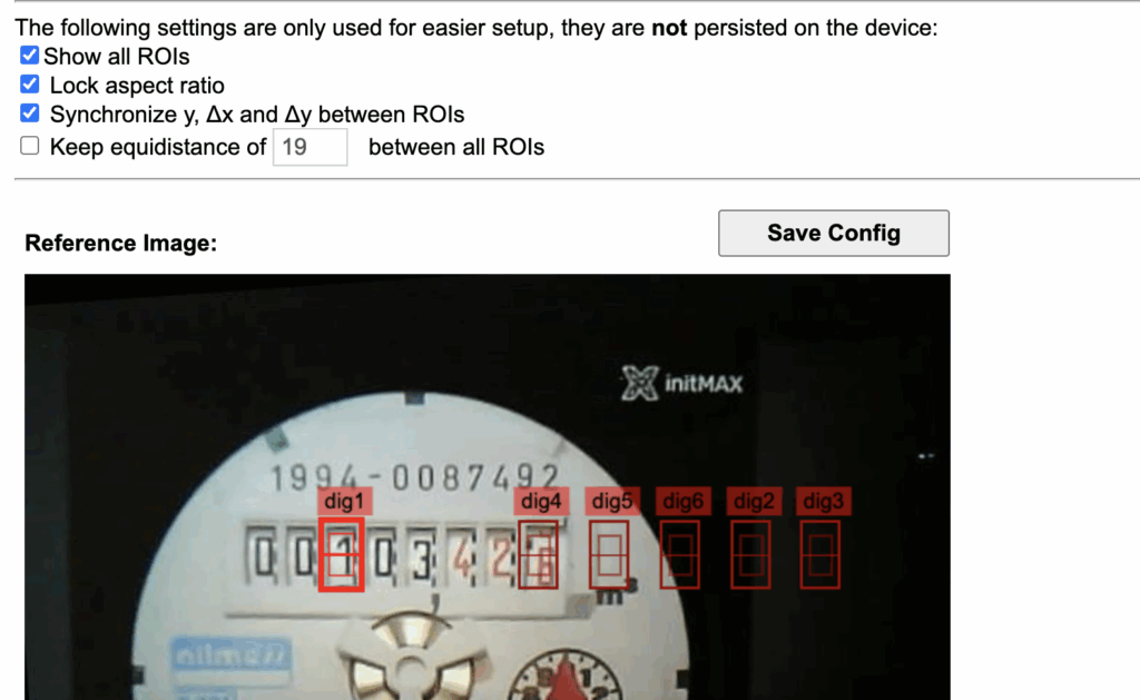
Next, check the option Keep equidistance of X between all ROIs – use the X value to fine-tune the spacing between the individual fields.
In our case, this “magic number” is 4.
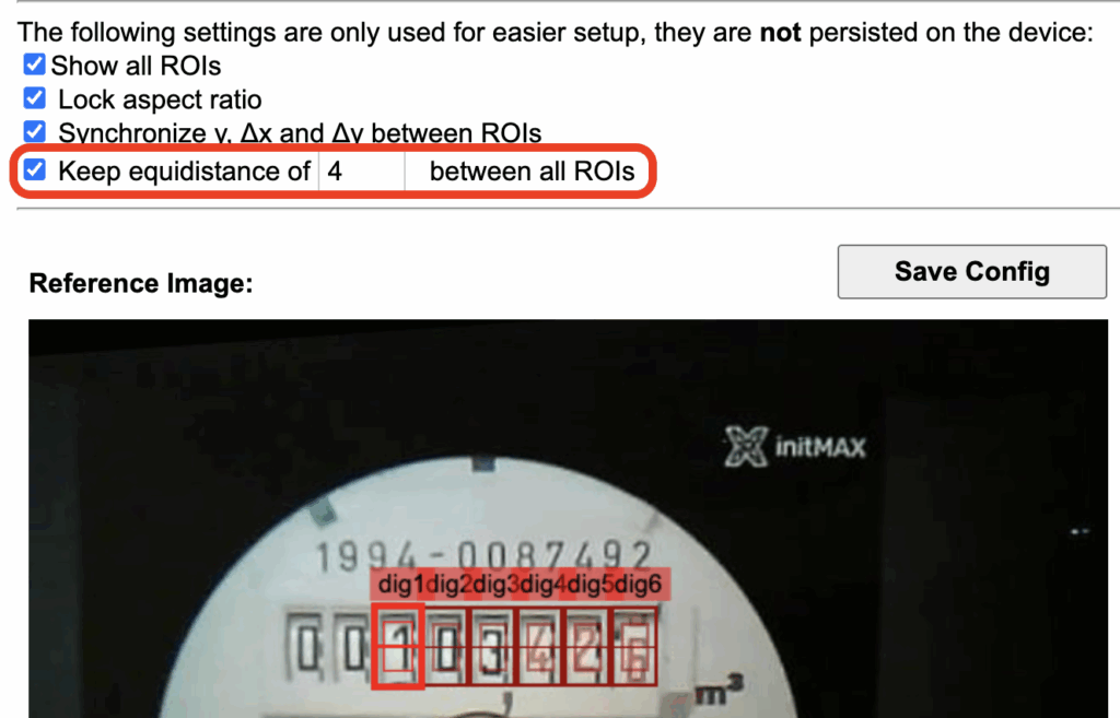
Once everything looks as desired – the digits are centered within all rectangles – click Save Config.
Then you can move on to the next configuration section by clicking the Next Step button.
Here, the situation is the opposite – we need to remove the analog fields so that only one remains.
The fields must be deleted from the end, so start by selecting ana4 and clicking Delete ROI.
Repeat this process for each remaining one until only ana1 is left.
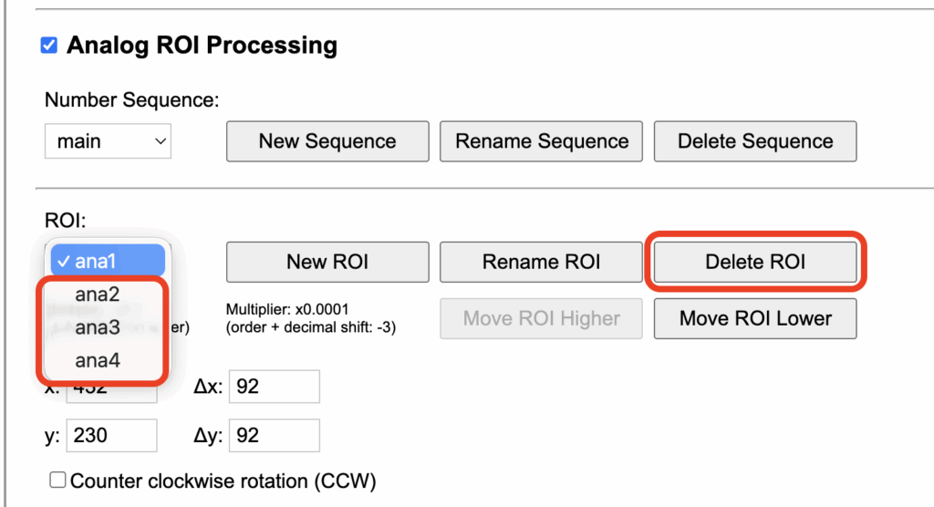
Then select ana1 and, on the image, mark the area of the analog dial. For easier orientation, you can place markers on the edges of the dial to get a more precise boundary.
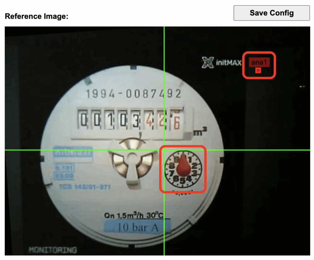
You can optionally fine-tune the position using the corresponding control buttons.
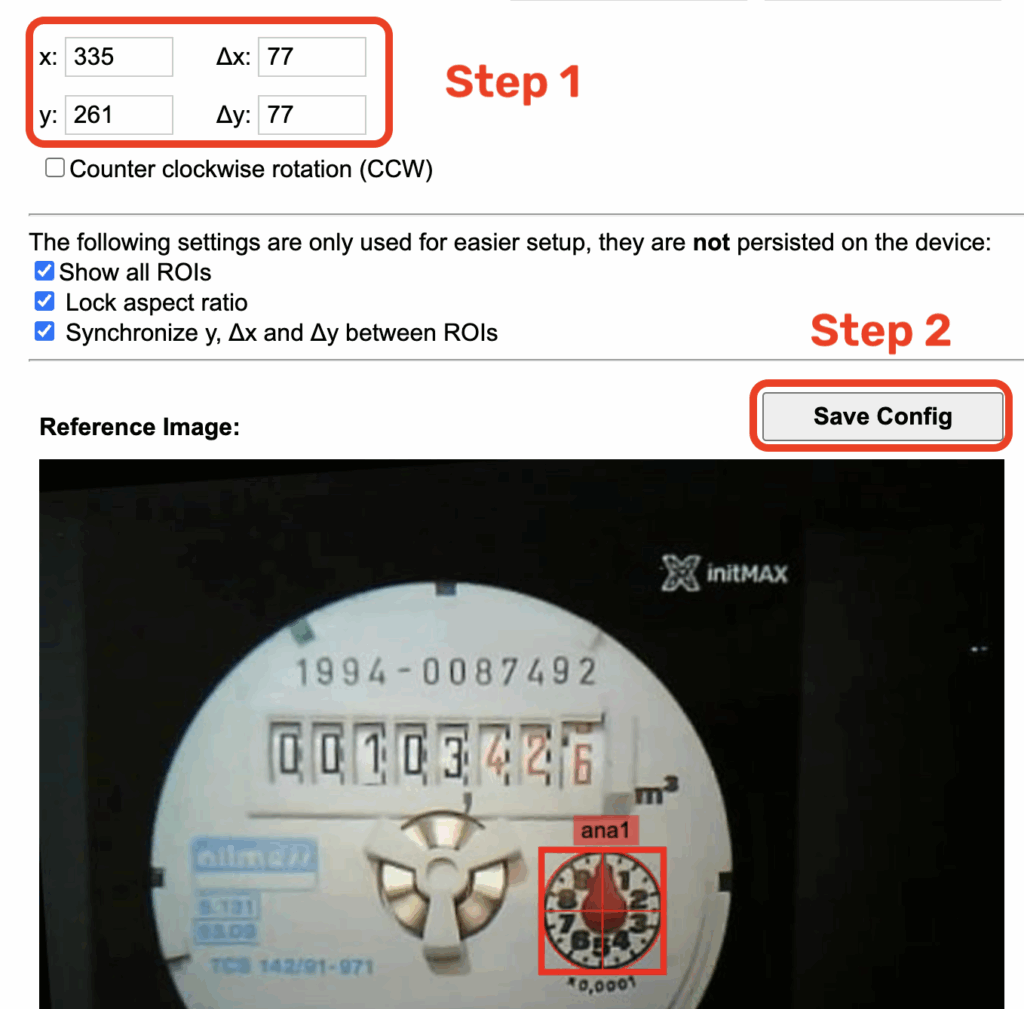
Once you’re satisfied with the precise placement, don’t forget to click Save Config. Then select Next Step.
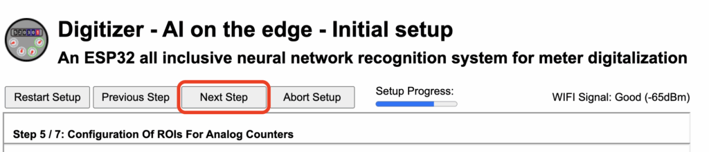
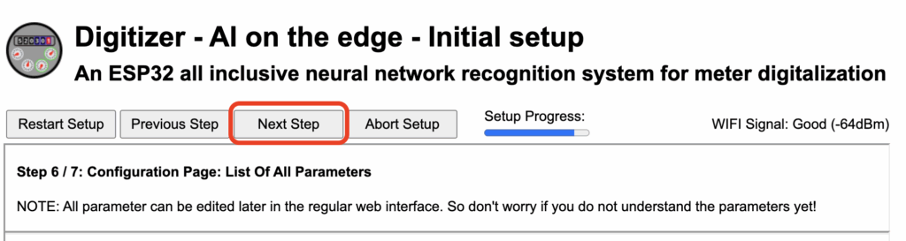
In the next step, there’s nothing else to configure, as everything needed was already set in the first step – so simply click Next Step.
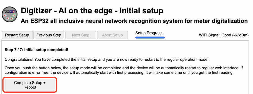
In the final step, press Complete Setup + Reboot – the device will restart, and after completing the reboot, it will automatically attempt to perform its first measurement.
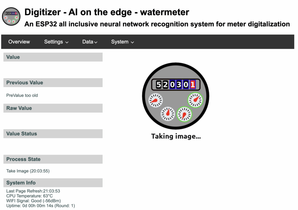
After the restart, the home page should appear. You’ll need to wait a short while – approximately 30 seconds – for the measurement to complete.
Final processed data
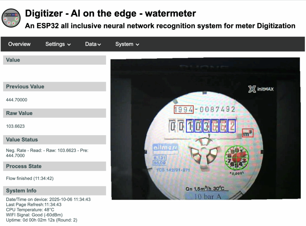
If necessary, you can repeat all the steps at any time in the Settings section.
The most common issue usually involves alignment markers. If the camera is being blocked, go to Settings > Configuration and increase the value of Auto Timer > Round intervalto, for example, 3, so that the system attempts data processing less frequently.
ZABBIX HTTP
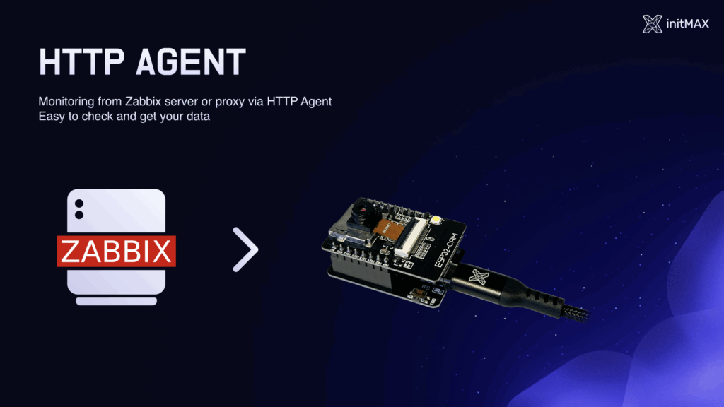
Log in to Zabbix using the credentials provided on the card. Find your host – the template has already been imported. The device is monitored via a proxy (Raspberry Pi).
On your host, link the template Meter_ESP32_by_HTTP and edit the {$ESP32.IP} macro (inherited from the template). Enter the IP address of your device into this macro and then save the changes.
You can also find the template on our GitHub: https://github.com/initMAX/Zabbix-Templates/tree/production/free/Meter_ESP32_by_HTTP – we’d really appreciate it if you gave us a follow.
After saving successfully, you can find an item named Meter HTTP RAW on your host.
Here, you can request test data, which should return a JSON response in approximately the following format:
{
  "main": {
    "value": "103.4218",
    "raw": "103.4218",
    "pre": "103.4218",
    "error": "no error",
    "rate": "0.023780",
    "timestamp": "2025-10-10T16:00:00+0200"
  }
}
This confirms that communication with the device is working properly, but it’s not the most efficient way to transfer data.
Since the values change roughly once per minute in our configuration, it’s better to use the second option – MQTT communication. Also, note the “calculate” item, which is used to compute daily consumption. In our lab, we currently don’t have enough data for this calculation yet.
ZABBIX MQTT
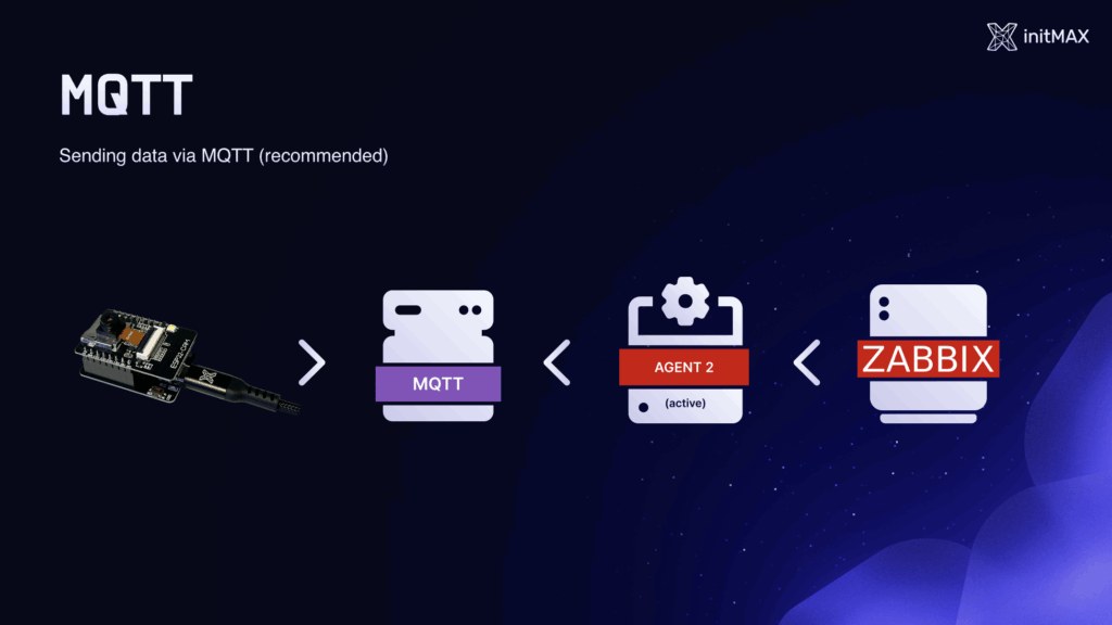
Before we can start working with MQTT, we first need to enable this function on the device. Open the following address on your device: http://10.10.0-3.XXX/edit_config.html.
Find the MQTT section and enable it by checking the corresponding checkbox.
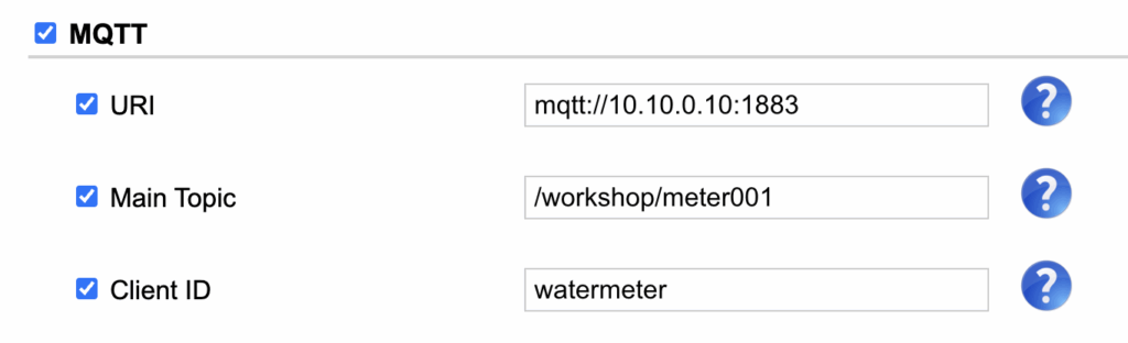
In the corresponding fields, enter the following values:
- URI: mqtt://10.10.0.10:1883
- Main Topic: /workshop/meterXXX
- Client ID: meterXXX
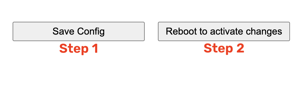
At the very bottom, click Save Config, then Reboot to activate changes to apply the new configuration.
In Zabbix, on your host, link the template Meter_ESP32_by_MQTT.
Then edit the {$WORKSHOP.NUMBER} macro (inherited from the template) – enter your workshop number and then save the changes.
You can also find the template on our GitHub: https://github.com/initMAX/Zabbix-Templates/tree/production/free/Meter_ESP32_by_MQTT – we’d really appreciate it if you gave us a follow.
After saving successfully, you can find an item named Meter MQTT RAW on your host. Here, you can request test data, which should return a JSON response similar to the previous example.
This confirms that communication with the device is working correctly, but it’s not the most efficient method of data transfer.
Since, in our setup, the values change approximately once per minute, it’s better to use the second option – communication via MQTT. Also, note the calculate item, which is used to compute daily consumption. In our lab, we currently don’t have enough data for this calculation yet.
If you have any questions, we’re of course fully available even after the workshop. We’ll be happy to help you fine-tune the configuration or answer any questions you may have about the topic.
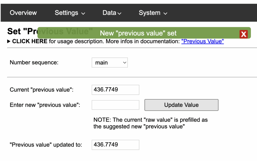
Tip for production deployment
You need to set the initial base value from which the meter will start counting.
Go to Settings → Set “Previous Value”.
Here, either click Update Value directly, or manually enter the desired value and then click Update Value.
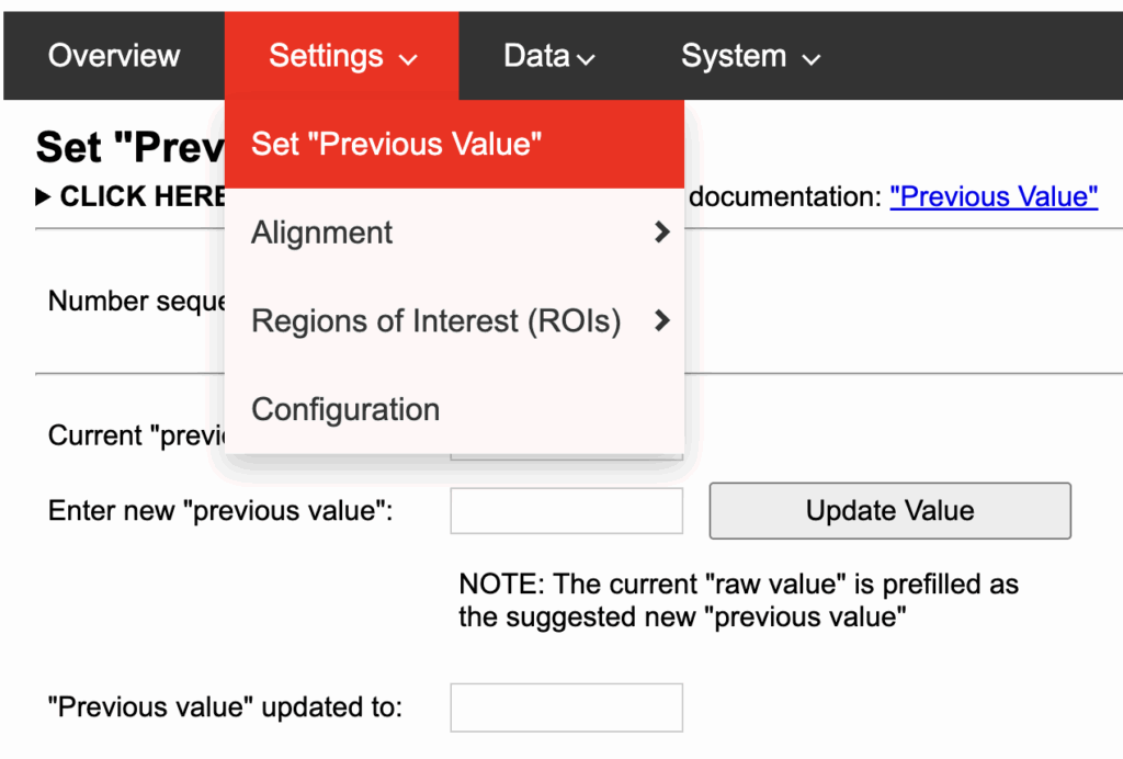
A confirmation message should appear.
Give us a Like, share us, or follow us 😍
So you don’t miss anything: